China Pipe Belling Machine Factory
Build The Socket Your Pipe Connection Requires
You give us the pipe standard, socket design, diameter range, wall thickness, and the rate you need to hit. We build the automatic belling and socketing machine around those numbers.
Smooth socket, gasket seat, and integrated seal each form differently, so the heating profile, forming tooling, and cycle time are matched to the socket you actually produce.
Send your socket drawing or pipe standard and you get the matching machine configuration, tooling list, and cycle time back within 24 hours.

Configured Around Four Inputs
Socket Or Joint Type
Smooth socket, gasket seat, or integrated seal.
Pipe Diameter
Tell us the OD range you run today.
Wall Thickness Or SDR
Wall thickness sets the heating and forming window.
Required Output
Give us your target in sockets per hour.
Explore Pipe Belling Machines
Fourteen sections, from the socket your standard actually requires to the run test you sign off on before shipment. Jump straight to whatever matches where your project sits right now.
Socket Requirements
Standard, design, dimensions
Belling Configurations
Machine built to your socket
Heating, Forming, Cooling
The three forming stages
Finished Socket Quality
Dimensions that must hold
Common Belling Problems
Wrinkles, ovality, shrink back
Socket And Gasket Systems
Gasket seat and seal types
Production Rate
Sockets per hour, line matched
Existing Line Integration
Adding to a running line
Size Change And Tooling
Mould change between sizes
Operation And Maintenance
Daily checks and service
Factory Manufacturing
Frame, machining, assembly
Inspection And Acceptance
Run test with your pipe
FAQ
Voltage, lead time, warranty
Define The Joint Before The Machine
A belling machine should be configured around the connection your finished pipe has to achieve. Before you look at models, pin down the pipe standard you build to, the socket geometry it calls for, your pipe dimensions, the seal system, and the rate you need to hold.
When those answers come first, the machine is built to produce your joint. When they come last, you end up correcting the machine instead of running it.
What Skipping This Step Costs You
- Tooling machined to a socket profile your standard does not accept
- A forming method that cannot handle your wall thickness without wrinkling or thinning
- A belling cycle slower than your extrusion line, so the line waits on the socket
Start With The Required Connection
Seven Answers Decide The Machine
-
1
Pipe Application
Pressure water, drainage, sewer, or electrical conduit.
-
2
Pipe Standard
EN, ISO, ASTM, or the local code your market enforces.
-
3
Joint Type
Smooth socket, gasket seat, or integrated seal.
-
4
Socket Geometry
Socket depth, entry angle, seat profile, and transition length.
-
5
Gasket Or Seal
Ring type, groove dimensions, and how the seal is placed.
-
6
Pipe OD And Wall Thickness
Your OD range and SDR set the heating and forming window.
-
7
Required Output
Sockets per hour, matched to the speed your line already runs.
Machine Configuration
Heating zones, forming method, cooling, clamping, and tooling are all decided by the seven answers above. Send them once and you get a configuration built around your joint, not a catalogue model you have to work around.
What We Need To Review
You will not have all seven of these on hand, and that is fine. Send what you have today and we come back with the two or three answers that are still missing before anything gets machined.
 Input 01
Pipe Standard
ISO, EN, ASTM, DIN, BS, or the local code your market enforces. It sets the dimensional and connection requirements your finished socket has to meet.
 Input 02
Socket Drawing
A drawing removes the guesswork on internal diameter, socket depth, and groove position. If you have one, send it first and most of this list becomes optional.
 Input 03
Pipe OD And Wall Thickness
Diameter alone is not enough. A 110mm SDR 11 pipe and a 110mm SDR 26 pipe form differently even though the OD reads the same on your order.
 Input 04
Spigot Dimensions
The socket has to accept the pipe end it mates with. This matters most when you assemble against pipe produced on another line or bought from another supplier.
 Input 05
Gasket Or Seal Drawing
Groove geometry and forming tooling are cut to the seal you actually buy. Send the profile and dimensions, or just the supplier name and part number.
 Input 06
Required Production Rate
Give us a target in sockets per hour. Heating, forming, cooling, and transfer are sized together so belling never becomes the point where your line waits.
 Input 07
Pipe Length
A 6m pipe and a 12m pipe need different handling around the same forming station. Send the length you actually run, not the nominal one on the spec sheet.
Three Stages, One Process
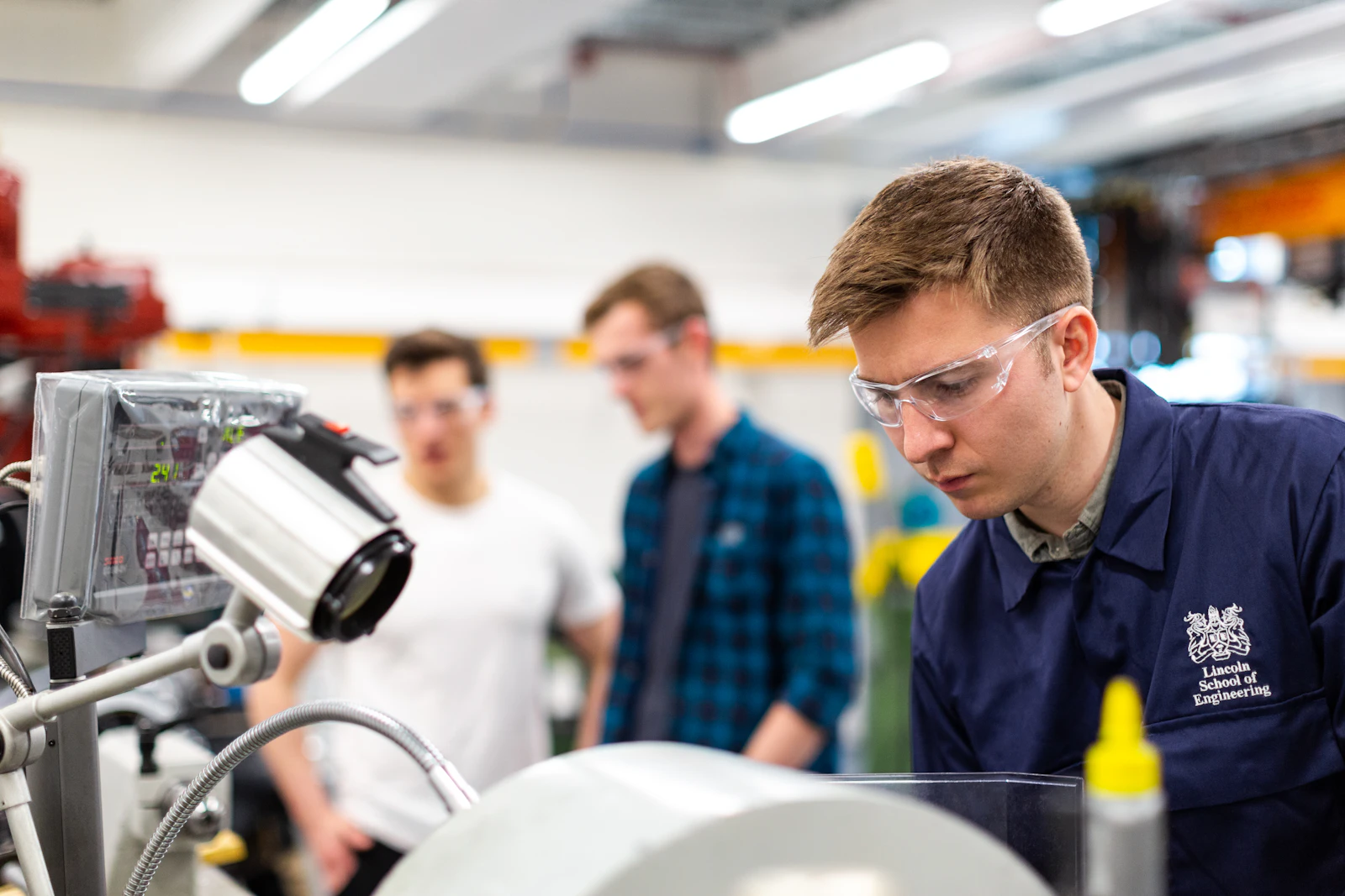
Stable socket dimensions come from the complete cycle, not from any single stage. The pipe end has to reach the right forming condition, take its shape from tooling matched to your socket, and cool enough to hold that shape after release. Material, diameter, wall thickness, socket geometry, and your production rate all change how the three are set.


Check The Socket After The Full Cycle
Do not judge the process while the pipe is still sitting on the forming tool. What matters is the socket after heating, forming, and cooling are all finished, measured on the rack, not in the machine. And it has to hold across repeated cycles, not on the one sample you kept for the photo.
What You Measure After Release
Judge The Machine By The Finished Socket
A belling cycle only counts as successful when the cooled socket holds the required dimensions and forms the connection you intended, cycle after cycle. Measure it after it has cooled and stabilized, not while the forming tool is still holding it in shape.
The Pipe Standard
Sets the dimensional target the socket lands inside.
The Approved Drawing
What the forming tooling gets cut to, nothing before it.
Agreed Inspection Criteria
What gets measured, when, against which tolerance.
Check The Critical Socket Dimensions
Hover a card on desktop, tap on mobile, to see what it affects.

Socket Internal Diameter
The bore has to give the fit your spigot or seal needs. Too tight and your crew fights every insertion on site, too loose and gasket compression drops away.

Socket Depth
Depth decides how far the mating pipe travels into the joint. Control it to the standard or the approved drawing, and hold it across the whole run, not just the first piece.

Groove Position
Move the groove a few millimetres along the axis and gasket seating changes, even though the socket still measures correct on diameter and depth.

Groove Geometry
Width, depth, and profile all have to match the specified gasket. Judge the groove against the gasket spec, never by how it looks in the socket.

Roundness
Ovality hides behind an average. It affects insertion, gasket compression, and site assembly even when the mean diameter reads exactly right.

Axial Alignment
A socket off the pipe axis is telling you about pipe positioning, tooling alignment, or the forming sequence. Treat it as a symptom, not a cosmetic issue.

Surface Condition
Read the surface together with the dimensions. A socket can look acceptable to the eye and still sit outside the geometry your standard requires.
Confirm The Actual Connection
Dimensions on a report tell you the socket is inside tolerance. They do not tell you the joint assembles. Follow the inspection with a real assembly check, using the mating components you actually ship with.
Smooth Sockets
Nothing holds this joint except the bore and the spigot fit, so assembly is where a wrong internal diameter finally shows itself.
What You Check
- Spigot insertion by your normal site method
- Insertion depth against the mark on the pipe
- Fit along the full engagement length
- Alignment of both pipes once assembled
Gasket Seat Sockets
Fit the gasket you actually buy, not a sample ring. Only the real seal proves the groove was formed correctly.
What You Check
- Gasket installation, how easily it goes in
- Seating all the way around the groove
- Groove compatibility with the specified profile
- Spigot insertion with the gasket in place
- Seal position after assembly, not just before
Integrated Seal Sockets
The seal went in during forming. The question is whether it stayed there once the socket cooled and the pipe was handled.
What You Check
- Seal position against the approved drawing
- Retention after cooling and after handling
- Socket geometry around the seal itself
- Spigot insertion through the seal
- Final assembled condition of the joint
Check Repeatability, Not One Good Socket
One acceptable sample proves the machine can make your socket. It does not prove your line will make it all shift. Run consecutive cycles, let them cool, then compare the finished sockets side by side. Critical dimensions and connection fit should stay inside the agreed acceptance criteria at the start of a run and hours into it.
What We Run Before Shipment
When The Finished Socket Is Not Right
Socket defects rarely come from one setting alone. The fastest way to find the cause is to start with the finished socket, then trace back through the incoming pipe, heating, tooling, forming, and cooling.
Socket Too Tight Or Too Loose
Finished socket ID and spigot OD
Heating condition, mandrel size, cooling shrinkage

Socket Becomes Oval
Incoming pipe ovality and pipe centering
Heating uniformity, tooling alignment, cooling

Socket Changes After Release
Cooling time and release condition
Heating level, wall thickness, forming time

White Marks Or Scratches
Pipe temperature and tooling surface
Expansion condition, alignment, pipe end preparation

PVC Yellowing Or Heat Damage
Heating temperature and exposure time
Heating distance, temperature distribution, pipe formulation

Gasket Groove Is Inconsistent
Groove tooling and forming position
Pipe centering, temperature, cooling, gasket profile
Before Adjusting The Belling Machine
Check the pipe entering the machine first. An out of square cut, an incorrect chamfer, excessive pipe ovality, or unstable pipe dimensions all show up in the finished socket. Changing belling settings will not correct an upstream pipe defect, it only hides it for a while.
Cut Pipe
Squareness
Chamfer
Ovality
OD and wall
Heating
Forming
Cooling
Finished Socket
Assembly
Find where the dimension begins to change before changing the machine settings.
The Socket Must Match The Joint
Two pipes with the same diameter can need completely different belling tooling if the joint design is different. Confirm the socket dimensions, groove profile, and forming process together with the mating spigot and, where it applies, the actual gasket or seal you buy.
Smooth Socket
No formed groove here, so everything rests on one relationship: the expanded socket against the mating spigot. Get that dimensional pairing right and the joint works. Get it wrong and no amount of cement will save the connection.
Socket ID and insertion depth follow the applicable pipe standard or your approved drawing, so the assembled joint lands on the fit your standard expects.
Socket drawing, spigot dimensions, pipe standard
Removable Gasket Seat
The machine has to form more than a socket diameter. It has to reproduce the groove that locates and supports the removable gasket, cycle after cycle, at the same axial position.
A groove that runs shallow, deep, or a few millimetres off position changes how the gasket sits and how the spigot enters. Review the gasket together with the socket drawing rather than treating the groove as a dimension on its own.
Socket drawing, gasket drawing or profile, spigot dimensions
Integrated Seal
The seal becomes part of the forming process rather than something fitted afterwards. Forming sequence, tooling, and seal position stop being three separate decisions and turn into one.
That means the configuration follows the specific seal system you run. Pipe diameter alone will not get you there, and neither will a general socket name.
Seal specification, socket drawing, pipe standard, forming requirement
Compare The Joint Before Choosing Tooling
Same pipe diameter, three different machines. What separates them is the structure the tooling has to form and the information you need to hand over before it is cut.
| Joint System | Socket Structure | Main Tooling Concern | What Should Be Confirmed |
|---|---|---|---|
| Smooth Socket | Smooth expanded bore | Socket ID and depth | Socket drawing and spigot size |
| Removable Gasket | Formed gasket groove | Groove profile and position | Gasket, groove and spigot dimensions |
| Integrated Seal | Seal incorporated during forming | Seal position and forming sequence | Seal system, tooling and socket drawing |
Swipe the table sideways on a phone.
If Your Drawing Says R Type Or U Type
These names get used across the market, but they do not describe the same socket geometry from one supplier or pipe system to the next. Two plants can hand us the same label and mean two different grooves.
Send the pipe standard or the socket drawing instead. It gives our engineering team something real to review the tooling and forming process against before your configuration is confirmed.
Send Any Of These
Match Belling Output To Your Pipe Line
A belling machine is sized by the number of pipes it has to process, not by extrusion output in kg per hour. Start from the actual count of cut pipes arriving at the station, then compare that demand against the complete belling cycle.


Four Figures Size The Machine
Extrusion output tells us how much material your line pushes. It says nothing about how many pipe ends land in front of the belling station every hour. These four do.
Pipes Per Minute
How many finished pipe lengths arrive from the cutter.
Sockets Per Hour
How many finished sockets the belling machine has to produce.
Pipe Outlets
Single, dual, or multiple extrusion outlets change how many pipes reach the machine at the same moment.
Pipe Length
Shorter lengths mean more pieces per hour through the same station, even at unchanged extrusion output.
What Sets The Belling Cycle
Your available output is not set by any one machine setting. It is set by the whole arrangement the pipe passes through, and by whichever stage in it takes the longest.
Heating usually takes the largest share, and it grows with diameter and wall thickness. Once heating alone decides your cycle, adding force or speed elsewhere changes nothing.
Additional Heating Stations
More than one pipe end heating at the same time, so the oven stops being the bottleneck.
Parallel Processing
Stages overlap instead of running strictly one after another, which shortens the effective cycle.
Multi Pipe Handling
Two or more pipes handled per cycle, which matters most when your line runs several outlets.
Check The Configuration Against These
Pipe OD
Changes heating, tooling, and handling requirements.
Wall Thickness
Drives both heating and cooling time, the two longest stages.
Pipe Length
Decides transfer and support around the forming station.
Pipes Per Minute
How many pipes actually arrive from your cutter.
Required Sockets Per Hour
Sets the minimum belling output the machine has to hold.
Number Of Outlets
Whether pipes reach the machine one at a time or in parallel.
Socket Type
Smooth, gasket seat, and integrated seal each form and cool differently.
Send those seven and we come back with the cycle time and the station layout that carries your line.
Find The Bottleneck First
Your line runs at the speed of its slowest station. If that turns out to be the belling machine, everything upstream is just producing pipe faster than you can socket it.
One Number Decides Your Line Speed
Cutting Output
Pipes leaving the cutter
Required Belling
Sockets your line needs
Belling Capacity
What the machine actually delivers
Your extruder and cutter can run all day. The line still leaves at 180. Those 60 missing sockets an hour are the machine choice, not the operators.
The fix is not a bigger motor. Heating capacity, number of heating positions, forming cycle, cooling time, and pipe handling all have to be reviewed together, because whichever one is longest becomes your new ceiling.

Send Us The Actual Pipe Count
Small diameter pipe, short lengths, dual outlets, or multi outlet extrusion all push the piece count up without changing your kg per hour at all. That is exactly where belling stations get undersized.
Give us the real count coming off the cutter and we review whether your application needs:
The target is simple. The belling machine processes the pipes arriving at it without becoming your new bottleneck.
Add Belling Without Rebuilding The Line
A belling machine goes into a line that is already running, so the review starts at your cutter and ends at your stacker. What matters is how the pipe enters, how it moves through the belling process, and how it leaves after socketing.
What We Check Before Confirming Layout
Incoming Pipe
Material, OD, wall thickness and pipe length
Cutter Interface
Discharge height, transfer direction, cut quality and chamfer
Machine Layout
Center height, available floor space and pipe flow direction
Utilities
Power supply, compressed air and cooling water
Downstream Handling
Stacking, collection or packing arrangement
A photo or short video from your cutter discharge toward the stacker, plus the center height you run at, answers most of this before we ask.
One Machine, Four Connections
Everything else on your line stays where it is. The belling machine takes pipe from the cutter side and hands it on to whatever you already stack or pack with.
Cutter
Already on your line
Pipe Transfer
Already on your line
Belling Machine
The machine being added
Stacker Or Packing
Already on your line
What Changes When You Change Pipe Size
Going from 110mm to 160mm is more than swapping one mold. What actually has to change depends on your pipe diameter, wall thickness, socket design, and gasket system.
Match every pipe size you run to its required tooling and process settings before the machine is configured, not after the first changeover eats a shift.


Plan Your Tooling Before Ordering
If you run several pipe sizes, send the complete size range together with the socket type for each one. We confirm which mandrels, molds, and gasket related tooling ship with the machine, so you know exactly what changes moving from one specification to the next.
Tooling ordered later costs you lead time you did not budget for. Ordered up front, it costs you one email now.
Confirm Two Things
How many tooling sets does your production range require?
What has to change when you move from one size to another?
Keep The Process Stable Between Runs
Stable belling does not come from the forming recipe alone. Heating surfaces, molds, cooling circuits, sensors, and transfer components all have to stay in the same condition from one run to the next, or the recipe that worked last week quietly stops working.
Confirm The Setup, Not Just The Recipe
Check the mandrel and mold actually installed match the pipe size and socket design you are about to run. Forming surfaces clean, no damage, no material buildup.
Most bad first pieces trace back to one of these four, not to the settings.
A Running Cycle Is Not A Healthy Machine
The automatic cycle will keep running long after the sockets stop being right. Watch the finished pieces, not the cycle light.
Watch For Change In
A gradual drift usually means heating element deterioration, tooling contamination, a cooling problem, sensor drift, or a change in the pipe arriving from upstream.
When results move away from the approved sample, find the cause before compensating with repeated setting changes. Chasing it with settings hides the fault until it becomes expensive.
Five Systems Worth A Regular Look
None of these are complicated. They are simply the five places where a slow change turns into a socket you have to scrap, and where a five minute check on a Monday saves an afternoon later in the week.
Heating System
Elements, temperature sensors, heating area
Uneven or unstable heating changes the forming condition even when the recipe on screen has not moved.
Mandrels And Molds
Forming surfaces, scratches, wear
Tooling condition shows up directly in socket surface finish and geometry, with nothing in between to absorb it.
Cooling System
Circuits, nozzles, water and air passages
Reduced cooling either stretches your cycle time or lets the socket change shape after release.
Transfer And Positioning
Supports, guides, sensors, transfer mechanisms
Looseness or drift here is where repeatable socket depth and alignment quietly go away.
Pneumatic Or Hydraulic
Cylinders, valves, hoses, seals, connections
Leakage or unstable actuation reaches both forming and transfer movements, usually at the worst moment.
Keep The Right Spares On Site
For continuous production, the commonly serviced components should be identified when the machine is delivered, not the week you need one. Depending on your configuration these usually include heating elements, temperature sensors, seals, bearings, and pneumatic sealing components.
Mandrels and belling molds sit in a different category. Manage them as production tooling, one set per pipe and socket specification, not as spare parts.
Built For The Socket You Need To Produce
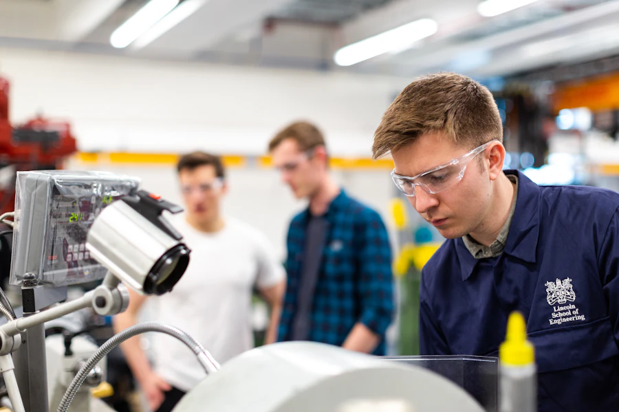
Mandrel and mold machining, heating oven assembly, pipe transfer, cooling, control cabinets, final assembly. Every stage is built around your approved socket specification.





18+
Years building extrusion line machines

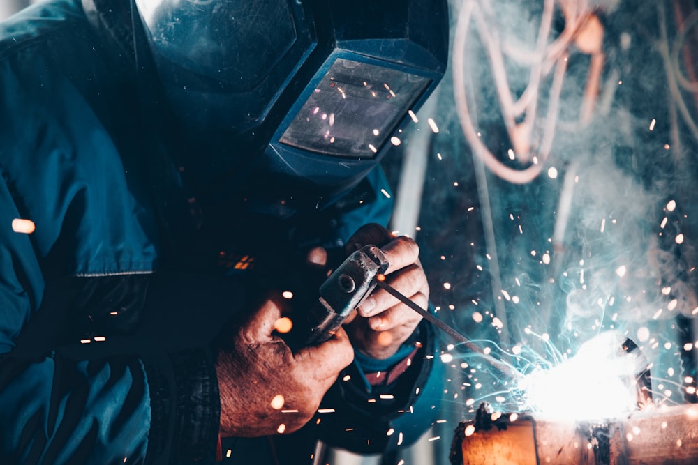
Want to see a specific stage? We send workshop photos and belling test videos on request, including the tooling cut for your socket.
Inspection Before The Machine Leaves Our Factory
Every belling machine is checked with the tooling and the production sequence your project actually needs. Pipe transfer, heating, forming, cooling, positioning, control functions, and the socket produced during the test.
When project samples and specifications are available, we run the test with real pipe, so the complete cycle is confirmed here rather than on your floor.
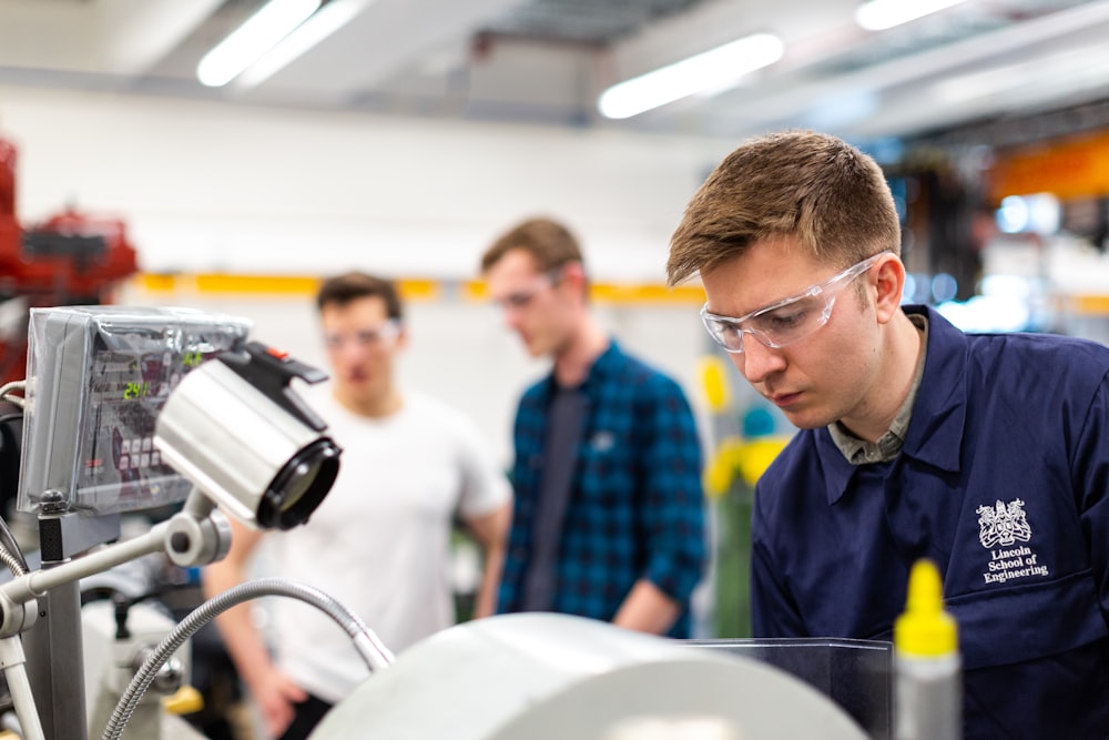
Heating System
Heating operation, temperature control, and the actual heating condition reached at the pipe end. Not the setpoint on the panel, the condition on the pipe.

Tooling And Positioning
Mandrel, mold, pipe support, and forming position confirmed against the socket your drawing calls for, with the tooling that ships with the machine.

Automatic Cycle
Loading, transfer, heating, forming, cooling, and discharge run through as one continuous sequence, the way your operator will run it.
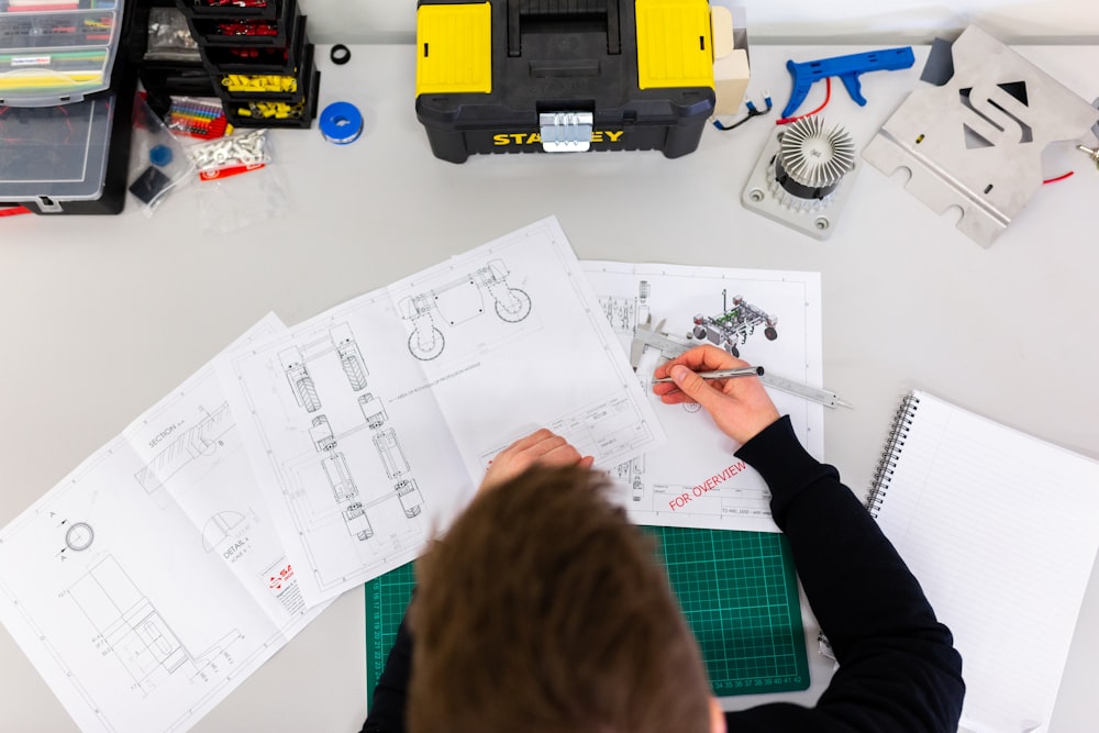
Finished Socket
Critical dimensions measured and the surface, roundness, and formed geometry inspected after cooling, on the rack rather than in the tooling.

Joint Assembly
Where it applies, the finished socket is assembled with the mating spigot, gasket, or seal system. The joint proves what the measurements only suggest.
Send pipe samples and your socket specification before the test and the machine is inspected against your joint. Ask for the run video, or come and watch it in person.
Questions Buyers Ask Before Ordering
Ten questions that come up in almost every belling project, answered the way we would answer them on a call. If yours is not here, send it over and Maggie will get you a straight answer.
01
What information do you need to select a pipe belling machine?
The most useful information is your pipe material, OD range, wall thickness or SDR, pipe length, socket type, pipe standard, and required output in sockets per hour.
For gasket or integrated seal applications, also send the socket drawing, gasket profile, or seal specification. Those documents let us check the tooling and forming process before a configuration is selected, rather than after.
02
What is the difference between a smooth socket and a gasket seat socket?
A smooth socket is formed without a gasket groove, and the connection relies on the fit between the socket and the mating spigot.
A gasket seat socket includes a formed groove for a removable sealing ring, so groove position, depth, and profile all have to match the gasket and the joint design.
The two need different tooling and forming requirements even when the pipe diameter is identical.
03
What is the difference between a gasket seat socket and an integrated seal socket?
A gasket seat socket forms a groove that receives a removable gasket. With an integrated seal socket, the seal becomes part of the forming process itself, which changes the tooling, the seal positioning, and the forming sequence.
For integrated seal production, the actual seal system and the socket drawing should be reviewed before the configuration is confirmed.
04
Can one belling machine produce different socket types?
It depends on the machine configuration and the socket designs involved. Moving from a smooth socket to a gasket seat or integrated seal socket can require different mandrels, external molds, gasket tooling, and forming sequences.
Some machines cover several socket types through tooling changes, others need a more specialized configuration. Compare the socket drawings before assuming one machine covers every joint you produce.
05
Can the same machine produce different pipe diameters?
Yes. A belling machine is normally configured for a defined diameter range, but each size can need its own mandrel, mold, and setup.
A diameter change can also mean adjusting pipe supports, heating conditions, forming positions, cooling settings, and machine recipes. Define your complete production size range before the tooling package is prepared.
06
How should belling machine production capacity be calculated?
In sockets per hour, or by the complete cycle time per pipe, not in kg per hour. Actual output depends on pipe size, wall thickness, socket type, heating time, forming time, cooling time, and the transfer arrangement.
For high speed or multi outlet lines, check the number of pipes arriving from the cutter as well, so the belling machine does not become your bottleneck.
07
Why does a socket change shape after it leaves the forming tool?
A socket can measure correct while the mandrel still supports it, then show springback, ovality, or dimensional change after release.
Common causes are insufficient or uneven heating, unsuitable forming conditions, inadequate cooling, early release, pipe wall variation, or unstable incoming pipe geometry.
Check final dimensions after the socket has cooled and stabilized, never in the tooling.
08
Can a belling machine be added to an existing cutting line?
Yes, but review the interface before the layout is finalized. We need cutter discharge height, pipe transfer direction, pipe length, cut and chamfer condition, available floor space, utilities, and your downstream stacking or packing arrangement.
For a running line, a layout drawing or a short production video is the fastest way to show how pipe moves from cutting into belling and on to the next stage.
09
What tooling needs to be changed when pipe size changes?
Depending on the application, a size change can involve the mandrel, external mold, gasket or seal tooling, pipe supports, and positioning settings. Heating, forming, and cooling recipes may change too.
If you produce several sizes regularly, list the required tooling sets by pipe size and socket type before the machine is ordered. Tooling added later costs lead time you did not plan for.
10
What should be checked during belling machine acceptance?
Both machine operation and the finished socket. The machine should complete the full transfer, heating, forming, cooling, and discharge sequence under the agreed test conditions.
After cooling, check socket ID, depth, groove geometry, roundness, alignment, and surface condition. Where it applies, assemble the socket with the mating spigot and the gasket or seal.
Base acceptance on repeated cycles, not one acceptable sample. Critical dimensions and connection condition should stay inside the agreed drawing, pipe standard, or criteria.
Still have a question about your socket, your line, or your tooling range? Ask it directly and you get a real answer, not a brochure.
Send Your Socket Details To Maggie
Pipe standard, socket type, OD range, wall thickness and target sockets per hour. That is enough for a real belling configuration and a quote back within 24 hours.

Maggie
Sales, QTech Machinery
Replies within 24 hoursEvery message from this page reaches me directly. Tell me what socket your pipe standard requires and how many you need per hour, and I come back with a machine configuration, a tooling list and a real quote, not a brochure.
If the problem on your line turns out to be the incoming pipe rather than the belling machine, I will tell you that before you order.
Maggie
Sales, Zhangjiagang Qinxiang Machinery Co., Ltd.
- Heating, forming and cooling sized to your socket and cycle time
- Mandrel, mold and gasket tooling listed by pipe size and socket type
- Belling test run with your pipe before shipment, dimensions recorded
- Your details stay private, no sales spam
Get Your Belling Configuration
Fields marked are required.