China Pipe Extrusion Die Head Factory
Custom pipe extrusion die heads for PVC, HDPE, PE and PPR pipe production, engineered around your pipe dimensions, material, required output and extruder interface.
Whether you are adding a new pipe size, replacing an existing die head or developing a new extrusion line, send us your pipe and extruder data. We will review the required tooling, connection and die head configuration before quotation.
New extrusion line or replacement for an existing extruder, both can be engineered to your project.
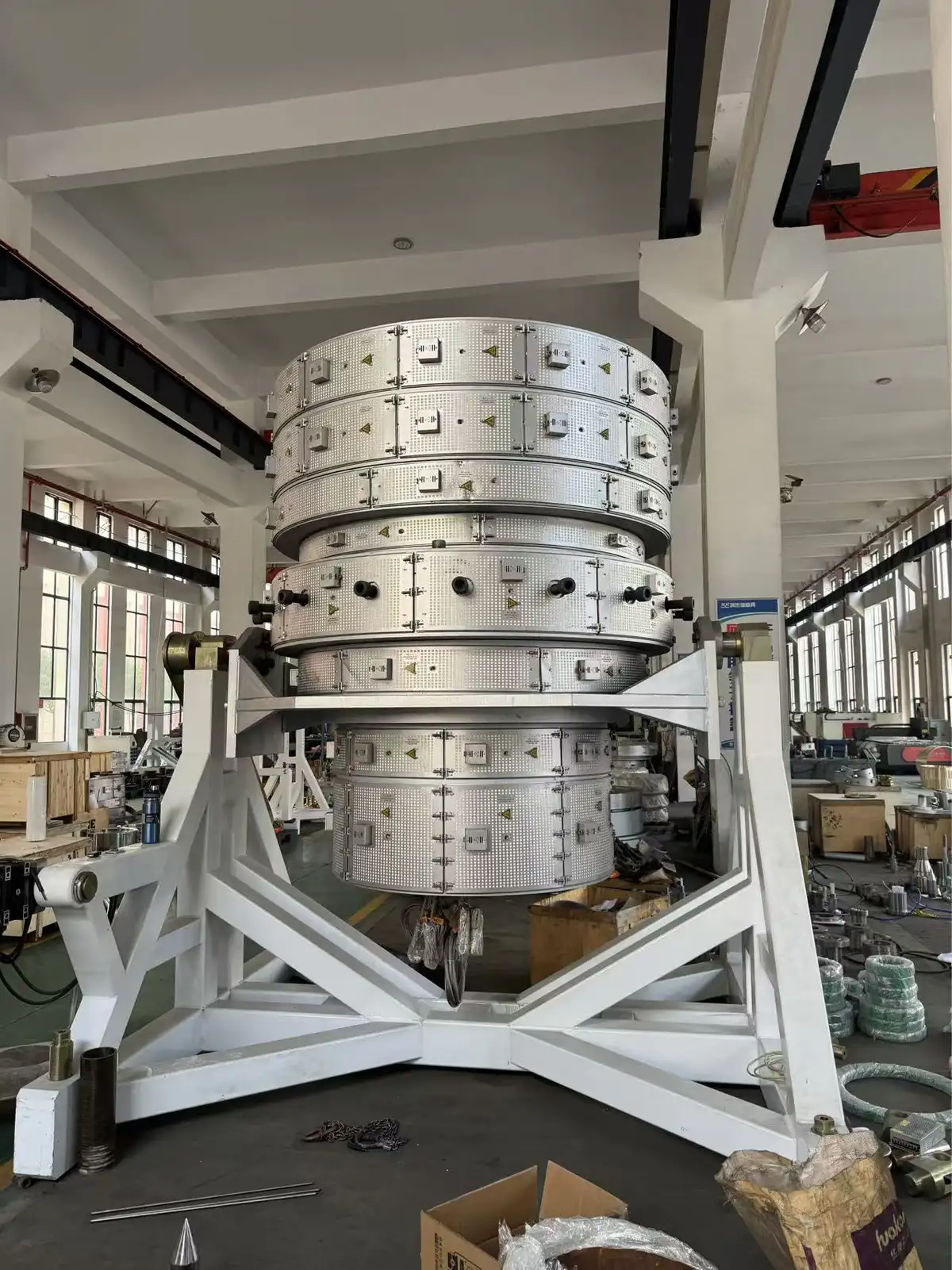
Material
PVC / HDPE / PE / PPR
Pipe OD Range
Send Your Required Sizes
Wall Thickness / SDR
According To Your Pipe Standard
Required Output
Based On Your Production Target
Get To Your Die Head Answer Faster
Start wherever your question is. Matching a die head to the extruder you already run, checking how wall thickness is held across the pipe, or sending drawings so we can quote the tooling you need.
Start With Your Pipe
OD, wall and material first
Die Heads We Manufacture
Types by pipe size and layer
Material Flow Design
PVC, HDPE, PE and PPR paths
Die Head Problem Control
Weld lines, sagging, burning
Wall Thickness Control
Even wall around the pipe
Extruder Compatibility
Fit to the machine you run
Size Change And Tooling
Adding a new pipe size
Multilayer Die Heads
Two and three layer builds
Color Stripe Options
Stripes and marking lines
Die Head Manufacturing
Machining, polishing, assembly
Inspection Before Shipment
Dimension and surface checks
Acceptance Before Shipment
Trial run and your sign off
Die Head FAQ
Drawings, lead time, warranty
Tell Us The Pipe You Need To Make
A die head is designed around the pipe it has to produce, the material running through it and the extruder it bolts onto. Send us the six items below and we can review the flow channel, tooling range and connection to your line before we quote anything.
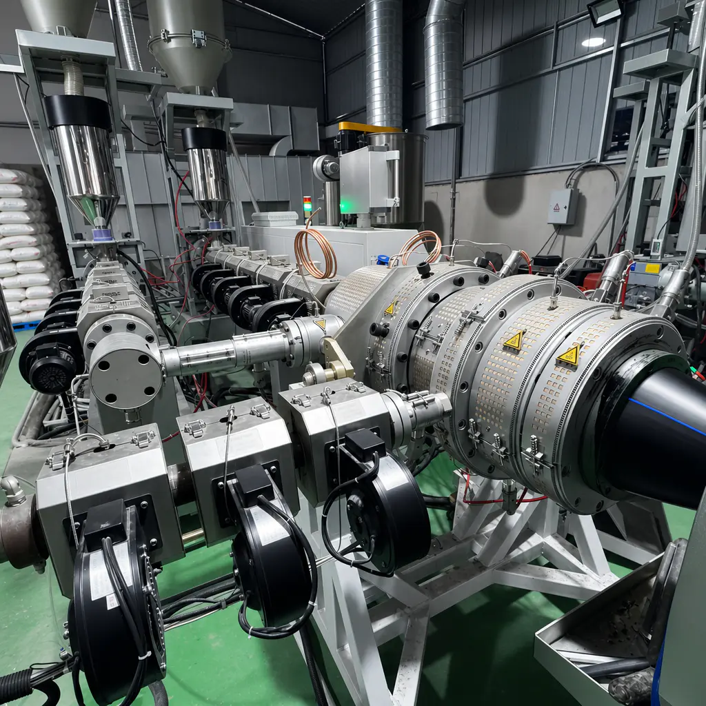
Pipe Material
01PVC / HDPE / PE / PPR / Other
The material you run decides the flow channel geometry, the melt distribution and the temperature zones inside the head. A channel cut for PVC will not treat HDPE the same way, so tell us the resin first.
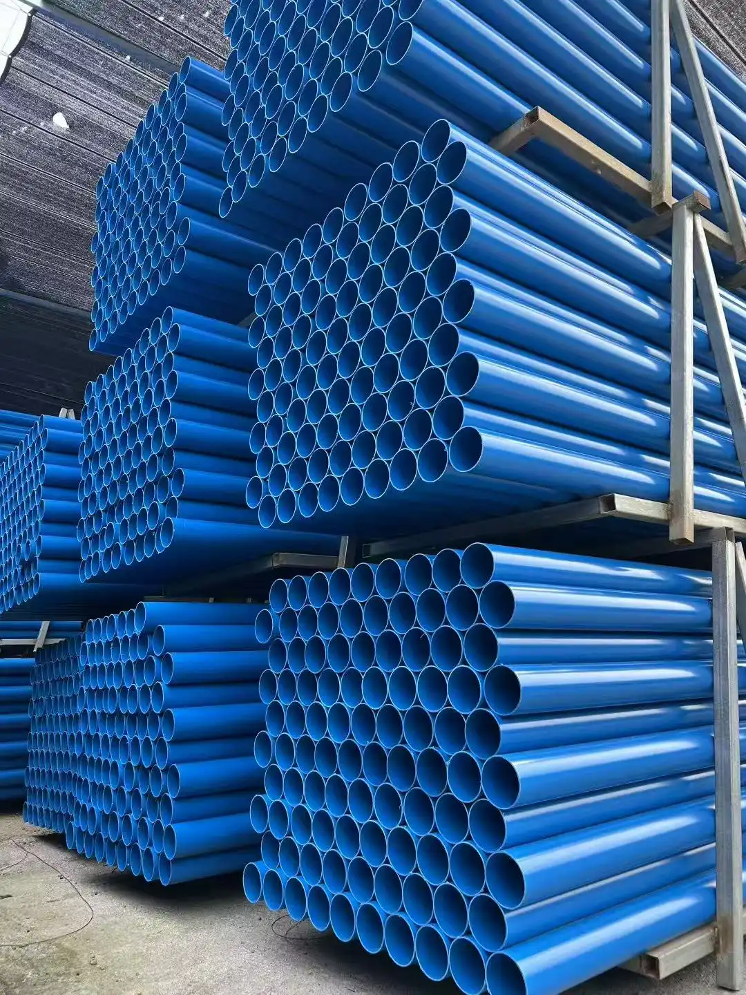
Pipe OD Range
02From Smallest To Largest Size
List every diameter you plan to produce, not only the size you need this month. The die body and the interchangeable tooling are planned together, so a size you add later does not force you into a second die head.
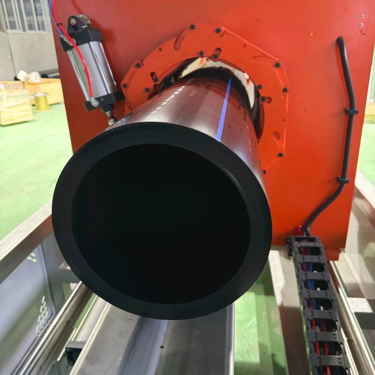
Wall Thickness Or SDR
03Provide Thickness Or SDR Range
Wall thickness sets the die gap, the tooling set and how the melt has to spread before it leaves the head. Send the full range you need to cover, including thin wall and pressure pipe if both are in your plan.
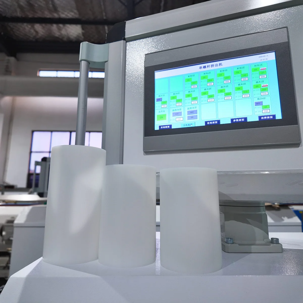
Pipe Standard
04ISO / DIN / ASTM / EN / Other
Tell us which standard your pipe is sold against, or simply send the finished pipe drawing. Dimensional tolerances get confirmed against your standard before any tooling is machined.
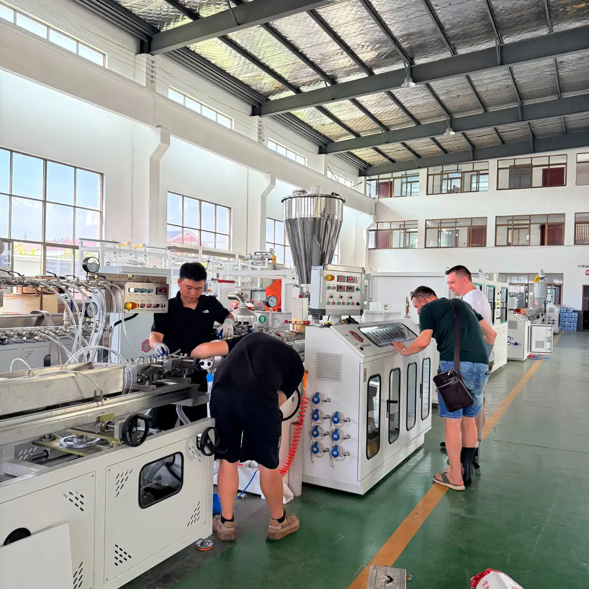
Required Output
05Target Output In kg/h
Your target output tells us whether the head can pass that melt flow without building extra head pressure or overheating the material. Undersize it and you pay for it every shift in slower line speed.
Production Type
06Single Layer / Multilayer / Stripe
Say the pipe structure at the start. Melt inlets, layer channels and stripe feeders are part of the die head design from the first drawing, not something that can be bolted on afterwards.
Replacing A Die Head On An Extruder You Already Run?
Then the connection matters as much as the pipe. A head that produces the right pipe but does not land correctly on your extruder outlet costs you a second round of machining and weeks of waiting.
Send the eight items on the right with your enquiry. We confirm the flange, the outlet dimensions and the melt path against your existing machine before we quote, not after you have paid.
What To Send With Your Enquiry
8 ItemsExtruder Brand And Model
Tells us the platform we are matching
Screw Diameter
Sets the melt volume reaching the head
Current Production Material
PVC, HDPE, PE or PPR you run today
Current Output In kg/h
Your baseline before the new head
Extruder Outlet Dimensions
The measurement most buyers forget
Flange Or Connection Drawing
Any format works, a sketch included
Photos Of The Existing Connection
Phone photos of the joint are enough
Problems You Have Now
Uneven wall, lines, sagging, low speed
No drawings on file? Send the photos and the model plate. We work back from what you have and tell you exactly which measurement is still missing.
Pipe Extrusion Die Heads We Manufacture
Different materials and pipe structures need different flow channels inside the head. Pick the pipe type you produce below. If you are not sure which configuration fits, send the pipe specification and we will tell you which one your line needs.
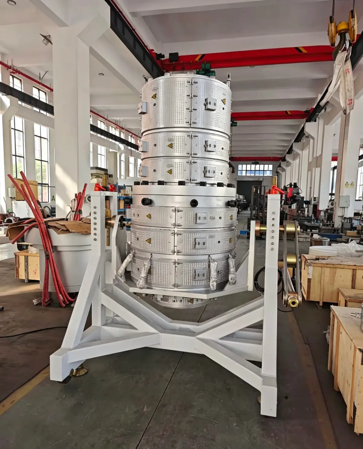
For Rigid PVC Water, Drainage And Conduit Pipe
PVC is heat sensitive and will burn where the melt sits too long. The flow channel is shaped so the material keeps moving evenly from the extruder outlet to the die gap, at the output you actually run.
Designed Around
- Your pipe diameter and wall thickness
- The output you need in kg/h
- Your PVC formulation and filler level
- The extruder connection on your line
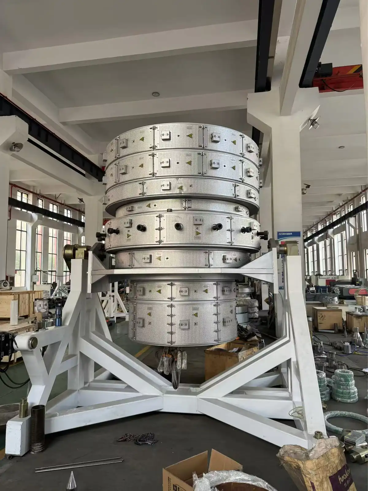
For PE And HDPE Pipe, Including Large Diameters
PE holds heat and moves slowly, so on bigger sizes the risk is sagging on the underside and visible weld lines. The spiral distribution and land length are set for your OD and SDR range, not for a generic size chart.
Designed Around
- Your pipe OD and SDR range
- Your target output per hour
- Melt flow rate of the resin you buy
- The capacity of your existing extruder
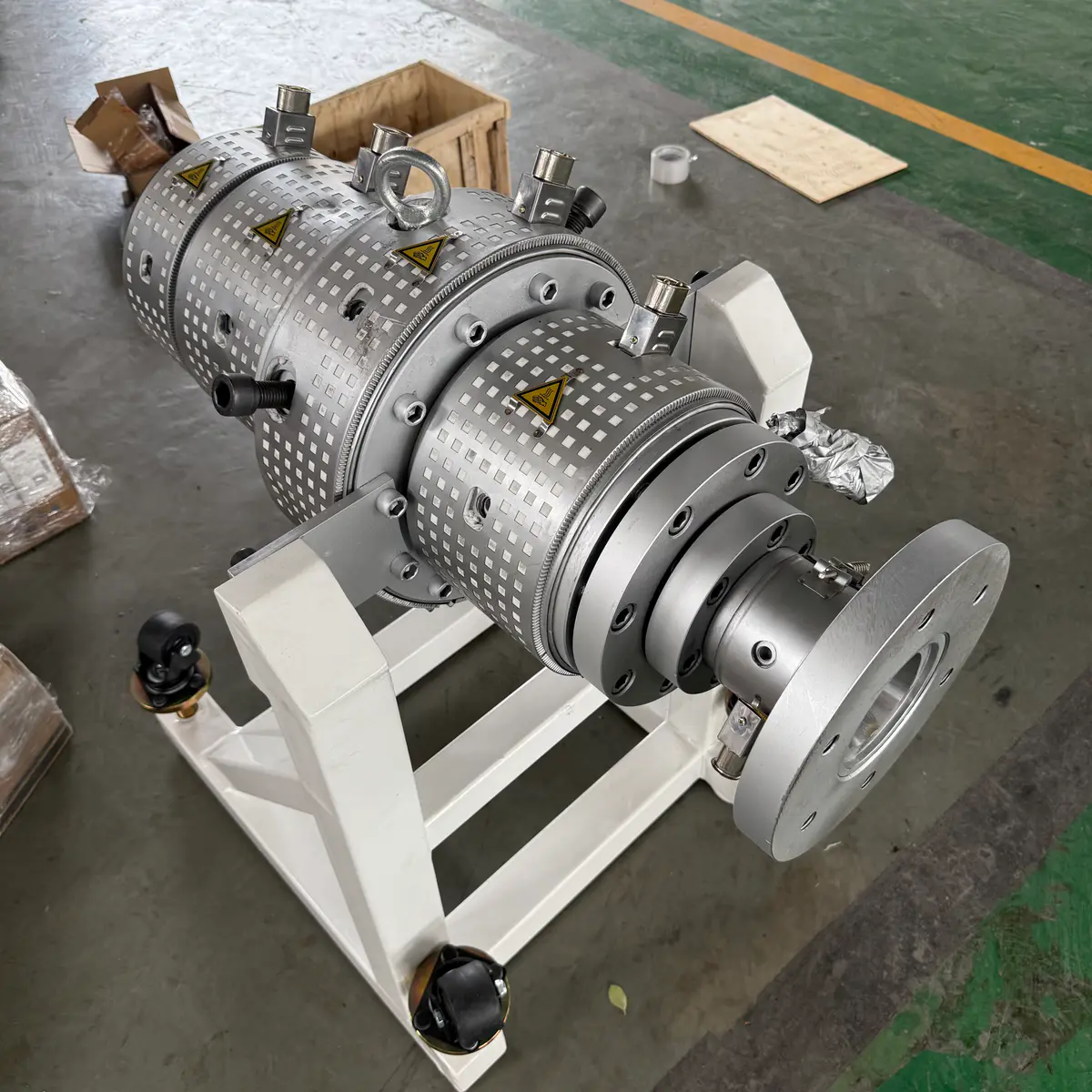
For PPR Hot And Cold Water Pipe
PPR pipe is judged on the shelf by its surface. The flow path and polished land are built to give you a clean inner and outer wall across the whole size range, from small plumbing sizes up to thicker pressure wall.
Designed Around
- The pipe size range you cover
- Surface finish your market expects
- Wall thickness and pressure class
- Production output you plan to hold
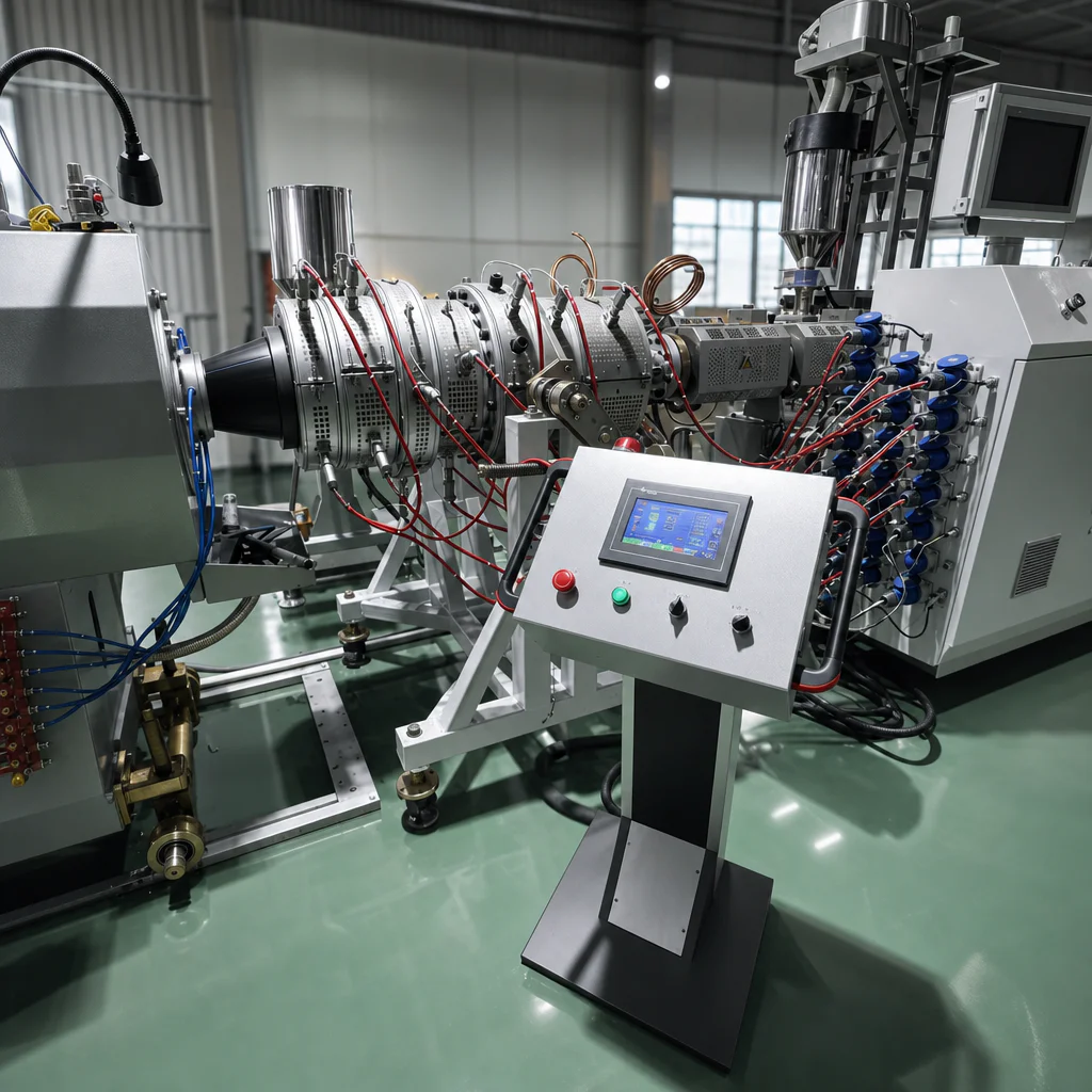
For Two Layer, Three Layer And Co-Extrusion Pipe
Each layer needs its own channel and its own share of the wall. Tell us the structure at the start, because the melt inlets and layer ratios are part of the first drawing and cannot be added to a single layer head later.
Designed Around
- How many layers your pipe has
- The material used in each layer
- Thickness ratio between the layers
- Output of your main and co-extruder
Not Sure Which Die Head You Need?
You do not have to pick the configuration yourself. Send your pipe material, OD range, wall thickness and target output, and we will tell you which head fits and why.
Installing on a line you already run? Add the extruder model or the connection drawing and we will check the fit at the same time.
Different Materials Need Different Flow Designs
PVC, HDPE and PPR do not behave the same way once they are melted, so the same internal geometry should not be reused across every pipe application. The flow channel is reviewed against your material, pipe dimensions, wall thickness and required output before anything is machined.
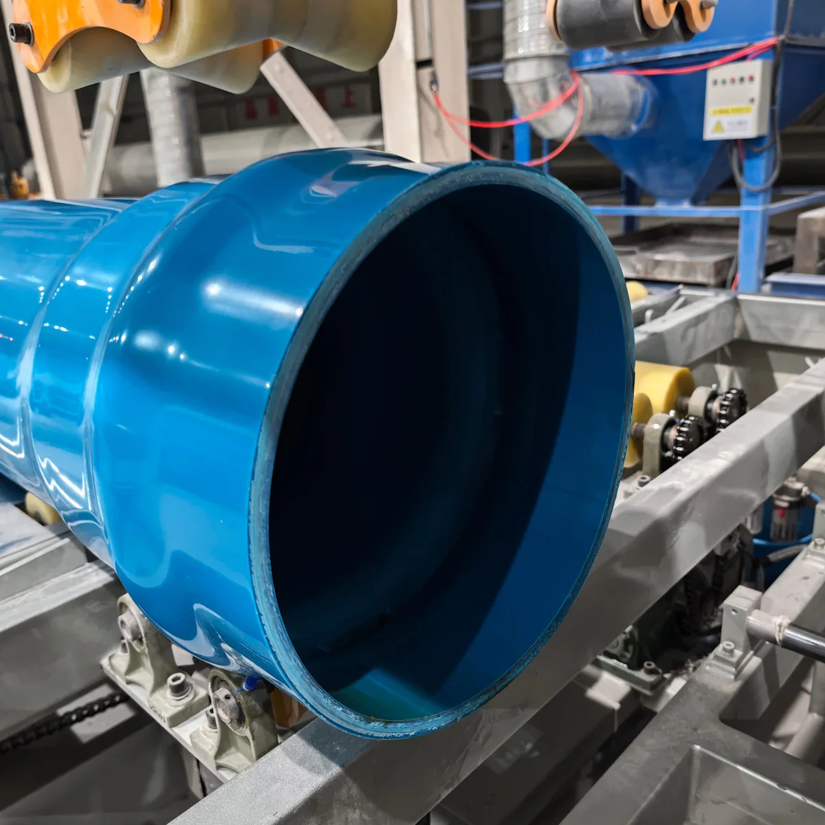
Keep The Melt Moving, Do Not Let It Sit
PVC does not forgive heat or time. Anywhere inside the head where material can pause, it starts to degrade, and you see it later as yellowing, burnt streaks or black spots in a pipe you cannot sell.
So the channel is shaped for flow continuity and short residence time, with the temperature profile and the split lines planned so your operators can open the head and clean it without a full shift of purging.
Design Focus
Spread The Melt Evenly All The Way Around
With PE the question is distribution. As diameter, wall thickness or output goes up, any imbalance around the circumference shows up as thin wall on one side and material you are giving away on the other.
The flow path is worked out together with your throughput, so distribution stays stable without pushing head pressure or melt temperature higher than it needs to be. On large diameter and thick wall pipe, output, distribution and wall adjustment have to be solved as one problem.
Design Focus
Surface And Wall Across Your Whole Size Range
PPR is bought on how the pipe looks and how consistent the wall is. Both come from stable distribution and a properly finished land, held not just at one size but across every size you change to during the week.
If more colors, a multilayer structure or extra specifications are in your plan for next year, say so before the head is designed. Building that in from the first drawing costs far less than modifying a finished head later.
Design Focus
Running more than one material on the same line? Tell us both and we will review whether one head can cover them or where a separate configuration pays for itself.
WhatsApp MaggieWhat Should A Pipe Die Head Control?
Forming the diameter is the easy part. What decides whether your line runs stable pipe is the flow, pressure, temperature and adjustment inside the head. If you are replacing an existing die head, start the engineering review from whichever of these six you recognise from your own floor.
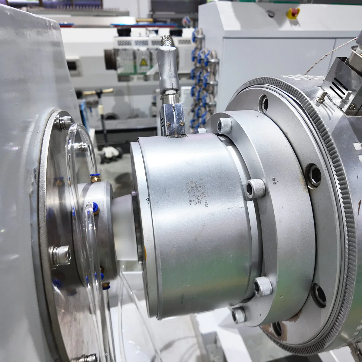 01
01
Uneven Wall Thickness
What You See One side of the pipe comes out consistently thicker than the other, so you overfeed material just to keep the thin side legal.
What We Review Circumferential flow distribution, die and mandrel centering, die gap and how practical the wall adjustment actually is for your operators.
02
Weld Or Flow Marks
What You See Lines running down the pipe that your customer notices before you do, sometimes with a weak point at the same position.
What We Review How the melt splits and rejoins inside the head, matched to your material, pipe size and output so the streams merge before they reach the die.
03
Excessive Melt Pressure
What You See Every attempt to push output higher sends die pressure and melt temperature up with it, so you back the line speed off again.
What We Review Whether the flow channel has real capacity for your throughput, and where restriction is adding extruder load without adding pipe.
04
Material Degradation
What You See Yellowing, black spots or burnt streaks appearing in pipe you have to scrap, usually worst after a long run or a stoppage.
What We Review Residence time, melt temperature and any dead zone where material can sit. This matters most on heat sensitive materials such as PVC.
 05
05
Long Purging Time
What You See A colour change eats hours and kilos of material because the old batch keeps coming back out of somewhere you cannot reach.
What We Review The flow path and how the tooling comes apart, so less material is trapped and cleaning between runs stops costing you production time.
 06
06
Difficult Wall Adjustment
What You See Every startup turns into an hour of chasing bolts before the wall is acceptable, and the result depends on who is on shift.
What We Review Melt distribution, die and mandrel centering, temperature stability and line alignment together, not the adjustment bolts on their own.
Recognise more than one of these? Send photos of the pipe, your current output and the extruder model. We will tell you which of them come from the die head and which are coming from somewhere else on the line.
Make Wall Thickness Easier To Set And Keep Stable
If your operators keep turning one side of the die just to pull the wall back into tolerance, the adjustment is probably not where the problem starts. Even wall comes from balanced melt distribution around the head, correct position between die and mandrel, and an adjustment range that actually suits the pipe size you are running.
When you measure, take readings at several points around the circumference. One value tells us the wall is out. Four tells us where the melt is going.
Start With Even Melt Distribution
Before the melt reaches the die exit it should already be spread as evenly as the head can manage, all the way around. Get that wrong and your operators spend the rest of the shift correcting at the die what the channel failed to do upstream.
That is why the flow channel is designed against your material, pipe size, wall thickness and required output, rather than copied from a standard drawing.
Give Your Operators Real Centering Adjustment
The position between die and mandrel decides the gap around the circumference. A centering system that works lets the operator correct distribution during setup with small, predictable moves instead of guesswork.
The adjustment range also has to match the tooling and the pipe sizes you actually run, so the same head stays workable when you change size.
Match The Tooling To Your Pipe Range
Pipe OD and wall thickness drive the die, the mandrel and the final gap. Send the complete OD and wall thickness range before tooling is finalised, not one size at a time.
With the full range in front of us we can tell you which components stay shared across sizes and which tooling has to change, so you know the real cost of adding a size later.
Wall Thickness Depends On More Than The Die Head
The head gives you the foundation, even melt flow and a workable adjustment. Final pipe tolerance is still decided by the whole line, so any review that stops at the die head is only half a review.
If a supplier tells you a new head alone will solve every wall problem on a running line, ask which of these six they checked first.
Extruder Stability
Output that swings shows up in the wall before it shows up anywhere else on the line.
Melt Temperature
Temperature drift changes how the melt spreads long before the operator sees it on the pipe.
Die Centering
What you set at startup, and whether it still holds three hours into the run.
Line Alignment
Head, calibration tank and haul-off sitting on one straight centreline, not close enough.
Vacuum Calibration
Vacuum level and water temperature set the final OD after the head has done its part.
Haul-Off Stability
Speed variation stretches the wall thinner in exactly the spot you were trying to fix.
Already Fighting The Wall On A Running Line?
Do not start by buying a new head. Send the six items below and we will work back from your actual pipe to tell you whether the die head is the cause, and what changing it would realistically give you.
Photos from your phone and measurements written on paper are enough to start.
Pipe Material
PVC, HDPE, PE or PPR, plus the grade if it is printed on the bag.
Pipe OD And Wall Thickness
Add the SDR or the pipe standard you sell against if it applies.
Current Output
Your real running kg/h, not the number on the original quotation.
Wall Thickness Measurements
Several points around the circumference. A single reading hides the pattern we need to see.
Existing Die Head Information
Drawing, tooling dimensions, or clear photos if no drawing exists.
What Goes Wrong
One side always thick, constant re-centering, or wall drifting when you change output.
Send what you have today. We will tell you which measurement is still missing before the review can be finished.
Replacing A Die Head On The Extruder You Already Run?
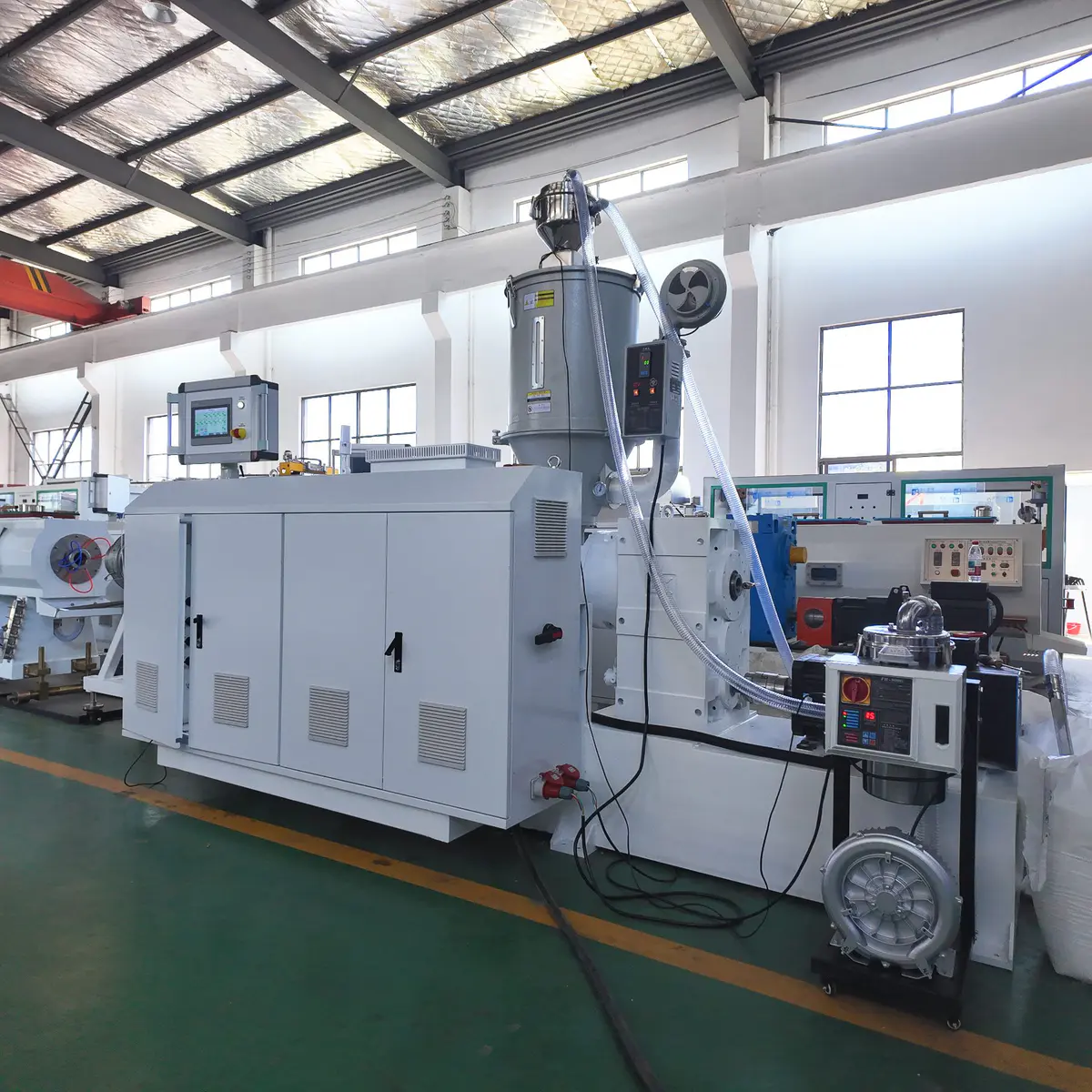
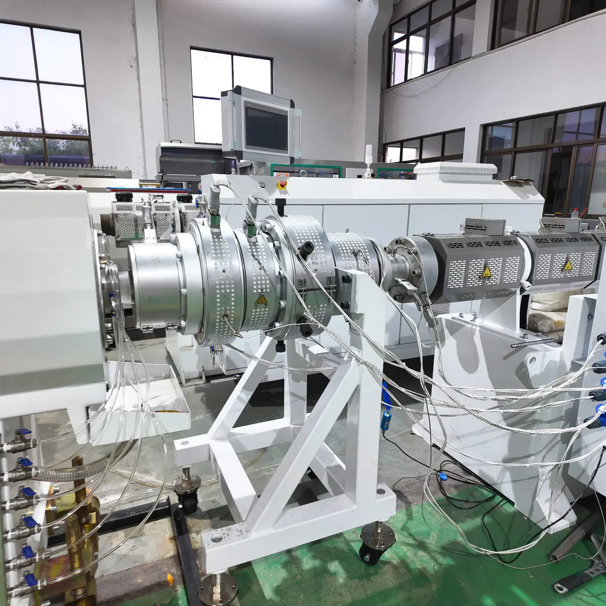
You probably do not need to replace the rest of the line. Before we design a replacement we go through four things with you: your existing extruder, the connection interface, the pipe you want to make and what is going wrong today. Work through the four steps below and you will have your enquiry ready in one go.
You See The Answers Before Anything Gets Machined
Once we have reviewed your data, you get four things back in writing. Not a price and a promise, but the actual engineering decisions, so you can check them against your own line before you approve anything.
Connection Method
Whether the head bolts straight onto your extruder, or whether a connection piece has to be designed. You hear this before you pay, not after delivery.
Die Head Configuration
The configuration we recommend for your material, pipe range and target output, with the reasoning behind it rather than just a model number.
Tooling Requirements
Which die and mandrel sets your pipe sizes need, which parts stay shared, and what a size you add next year would actually cost you.
Interface Drawing
Connection dimensions on paper, confirmed by you before manufacturing starts. Your maintenance team can check the fit while the head is still a drawing.
How It Runs
Start the review with whatever data you have on hand today. Nothing is machined until you have signed off the interface.
One Die Head, Multiple Pipe Sizes
If several diameters are in your plan, give us the complete range before the head and tooling are finalised. Depending on your material, range and design, one die body can often cover a group of sizes with only selected tooling changed between them. Deciding that at the start is what stops you paying twice.
What Changes When You Change Pipe Size?
Swipe or use the arrows to see all four
01
Often Stays
Die Body
The main body spreads the melt before it reaches the forming area. Across a sensible group of sizes you can usually keep the same body, which is where the saving is.
Whether that works for your range depends on how wide the diameter spread is, the output you need and the material you run.
02
Changes
Die Or Bushing
The outer forming tooling sets the annular opening together with the mandrel, so it is the part that most directly decides your finished outside diameter.
A different pipe OD, or a wall thickness range far from the current one, normally means a different die set.
03
Changes
Mandrel Or Core
The mandrel forms the inside of the melt annulus and works as a pair with the die. The two are specified together, never separately.
When pipe size or wall thickness moves significantly, the matching mandrel usually has to move with it.
04
Downstream
Calibration Sleeve
This one sits in your sizing system, not in the die head, which is exactly why it gets forgotten when a new size is planned.
Change the pipe diameter and the calibration tooling has to match the new finished size, or the head you just bought cannot be used.
Send the full list of diameters and wall thicknesses you want to cover, including the ones you are only considering. We will come back with which parts stay shared and what each extra size adds to the tooling cost.
What Can Be Reused, And What You Pay For Twice
There is no single answer that covers every pipe range. Before we quote, we go through your complete production plan and sort the components into three groups, so you can see the real tooling package instead of a single line item.
Reusable
Components that stay in place across several of your planned pipe sizes. This is the part of the package you buy once, and the reason the full range is worth confirming early.
Size-Specific
Tooling that has to change with the pipe diameter or wall specification. You will own one set per size, so it is better to see the whole list now than to discover it one order at a time.
Needs Review
Components where the answer depends on your material, your output and how far apart the pipe sizes sit. We tell you which way it goes rather than leaving it vague in the quotation.
Plan Your Future Sizes Before You Order
Say you run 63mm today, and 90mm and 110mm are already on the plan for next year. Put all three in the first enquiry.
We then design around the full range instead of around your first pipe size, and you find out now whether one die body covers all three or where a second package becomes unavoidable.
63mm
Running Now
90mm
Planned
110mm
Planned
Please Send
Pipe Material
PVC, HDPE, PE or PPR.
Complete OD Range
Current sizes and planned sizes in the same list, including the ones you are still deciding on.
Wall Thickness Or SDR
For each specification that matters to your customers.
Required Output
Especially where the target output is different from one pipe size to the next.
Existing Tooling
Drawings or photos of anything you want to keep using. We will tell you whether it is worth keeping.
The Three Costs Worth Checking
A tooling quotation only shows you the first of these. The other two get paid on your floor, every time you change specification, for as long as you own the head.
Tooling Cost
What extra tooling does each pipe size actually require, and which of it is a single set rather than a full package?
Changeover Work
Which components have to come off, get replaced and be re-adjusted, and how many people does that take?
Production Downtime
How much of the line has to be reset when you move to another specification, and what does that hour cost you?
Send the full size range and we will answer all three in writing, before you approve anything.
Multilayer Pipe Die Heads
For two layer, three layer and other co-extrusion structures, the head is designed around the material, thickness and output of each layer, not around the finished diameter alone. Send your planned structure with the main and co-extruder data and we will review the melt arrangement, layer distribution and connections before confirming anything.
Each layer needs its own channel and its own share of the wall. That arrangement is fixed in the first drawing and cannot be added to a single layer head later.
What We Need From You
Six items and the review can start. If any of them are still undecided, say so and we will design around the range instead of a single point.
Number Of Layers
Two layer, three layer or another structure you have in mind.
Material Of Each Layer
Virgin, recycled or a specified grade. Name it per layer, not for the pipe as a whole.
Pipe OD And Wall Thickness
The full range you plan to run, with the SDR or standard if it applies.
Target Layer Ratio
Thickness or percentage per layer. This is what decides your material cost per metre.
Main Extruder Output
The kg/h your main machine delivers, at the size you actually run.
Co-Extruder Output
Per co-extruder. A thin outer layer still needs a machine that can hold it steady.
Why These Six
Different materials melt and behave differently. The flow channels and melt inlets are arranged around your actual material combination and the output of each extruder, so a layer ratio that works on paper also holds on the line.
Installing on a line you already run? Add the extruder model, outlet dimensions and flange drawing and we will check the interface in the same review.
How The Review Runs
Planning Color Stripe Pipe Production?
Stripes are built into the die head, not applied afterwards. The question that changes the design is not which colour you want, it is how many stripes and where they sit around the pipe. Tell us the layout and the co-extruder data and we can review the arrangement.
How Many Stripes, And Where?
Each stripe needs its own feed inside the head
1 Stripe
The common identification marking. One co-extruder feed, one channel through the head to the die land.
2 Stripes
Visible from either side once the pipe is in the trench. Two feeds, balanced so both stripes hold the same width.
4 Stripes
Readable at any rotation. Four feeds have to be distributed evenly, which is where a stripe head differs most from a plain one.
Custom Layout
Uneven spacing, different widths, or a position fixed by your pipe drawing. Send the drawing and we work from it.
Stripe Colour On The Finished Pipe
Examples from production, not a colour chart
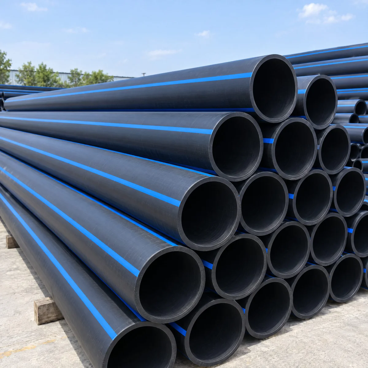
Black Pipe, Blue Stripe
Potable water marking
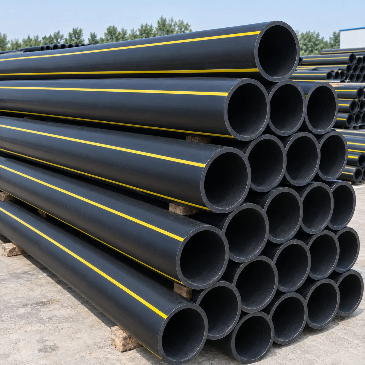
Black Pipe, Yellow Stripe
Gas distribution marking
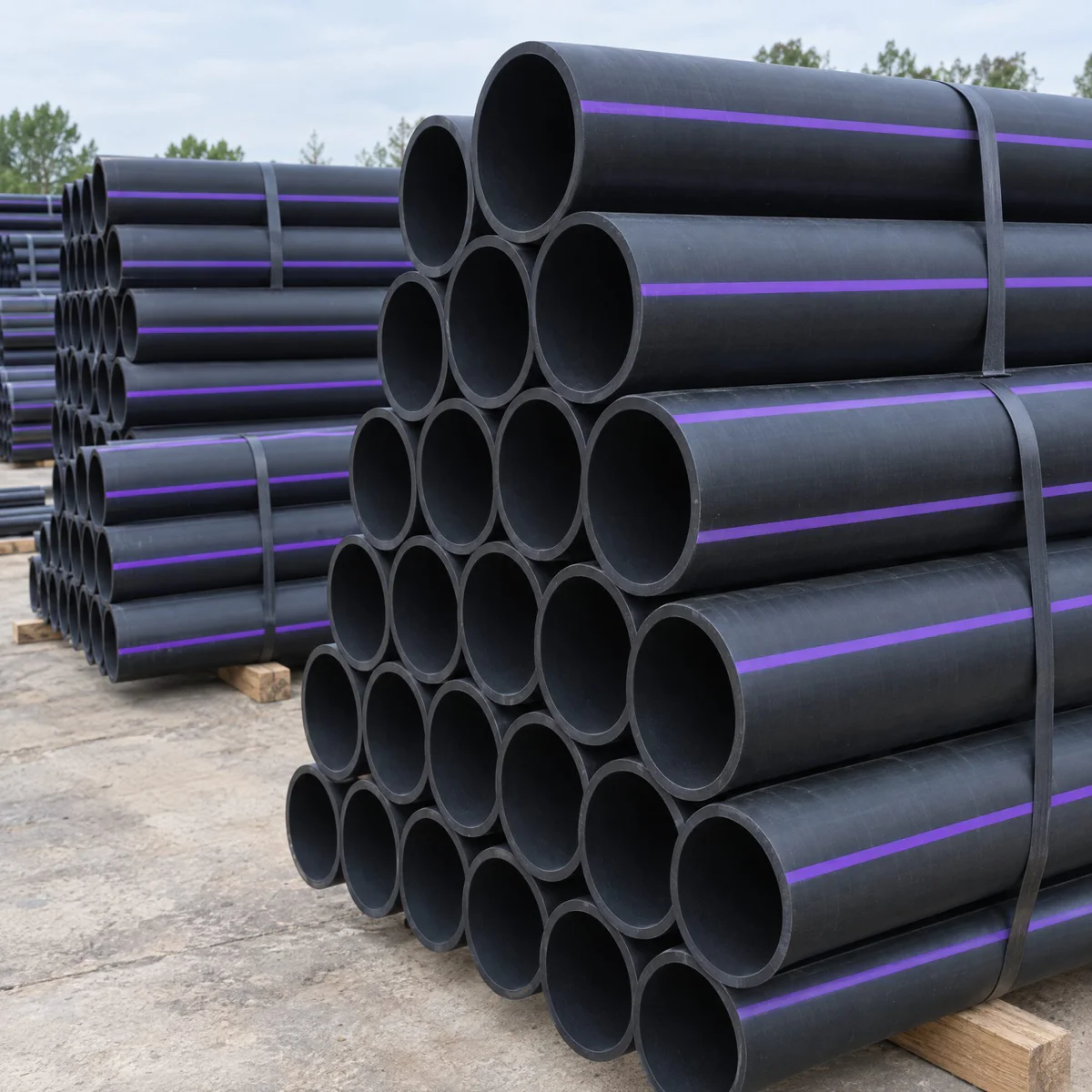
Black Pipe, Purple Stripe
Reclaimed water marking
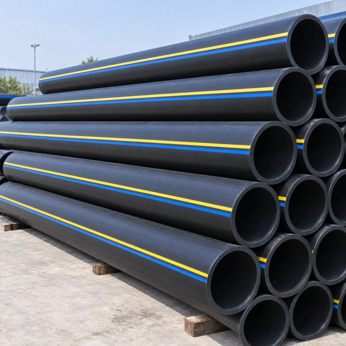
Other Custom Stripe
To your drawing or sample
Colour shown for reference. Final colour follows the specified standard, masterbatch reference or approved sample, never a screen image.
Send a photo or drawing of the pipe you need to match. Stripe count, position and width are all we need to start the layout review.
What We Need To Configure Your Stripe Die Head
Two things sit side by side here. The production data that decides the head, and the way you pin down the colour so nobody is guessing from a screen.
Production Data
Six items. If the layout is still open, send the pipe drawing and we work backwards from it.
Stripe Quantity
How many stripes around the pipe. This is the item that changes the head structure most.
Stripe Position
Evenly distributed, or at the angles fixed by your pipe drawing.
Stripe Width
The required width in mm, or a piece of the finished pipe you need to match.
Stripe Colour
Specified one of the four ways on the right, if your market fixes the colour.
Pipe OD And Wall Thickness
The full range you plan to run, since stripe width scales with pipe size.
Co-Extruder Output
Model and output. For an existing line, add the connection information as well.
Four Ways To Specify The Colour
Any one of these is enough. Two is better, and a physical sample settles every argument.
RAL Code
The fastest option when your pipe standard names one.
Masterbatch Code
The reference you already buy. Tells us the material as well as the colour.
Physical Sample
A short piece of the pipe you need to match. Nothing beats it.
Pipe Standard
If the stripe identifies the application, the standard usually fixes the colour for you.
Match The Pipe Standard
Where the stripe colour identifies what the pipe carries, send the applicable standard or the required colour specification. We would rather read it than assume it.
Match The Stripe Material
The stripe material has to be compatible with the main pipe material and with the processing conditions you actually run. A stripe that will not bond is worse than no stripe at all.
How The Review Runs
Send the pipe drawing and the co-extruder data together and the whole review runs in one pass.
From Engineering Drawing To Finished Die Head
Your head is machined against the confirmed pipe specification, tooling requirements and equipment interface. Critical dimensions and mating surfaces are checked as the work moves, not once at the end.
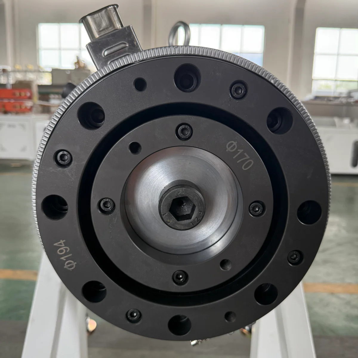
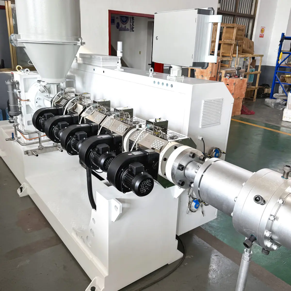
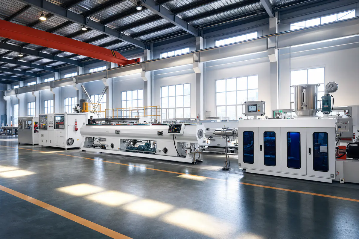
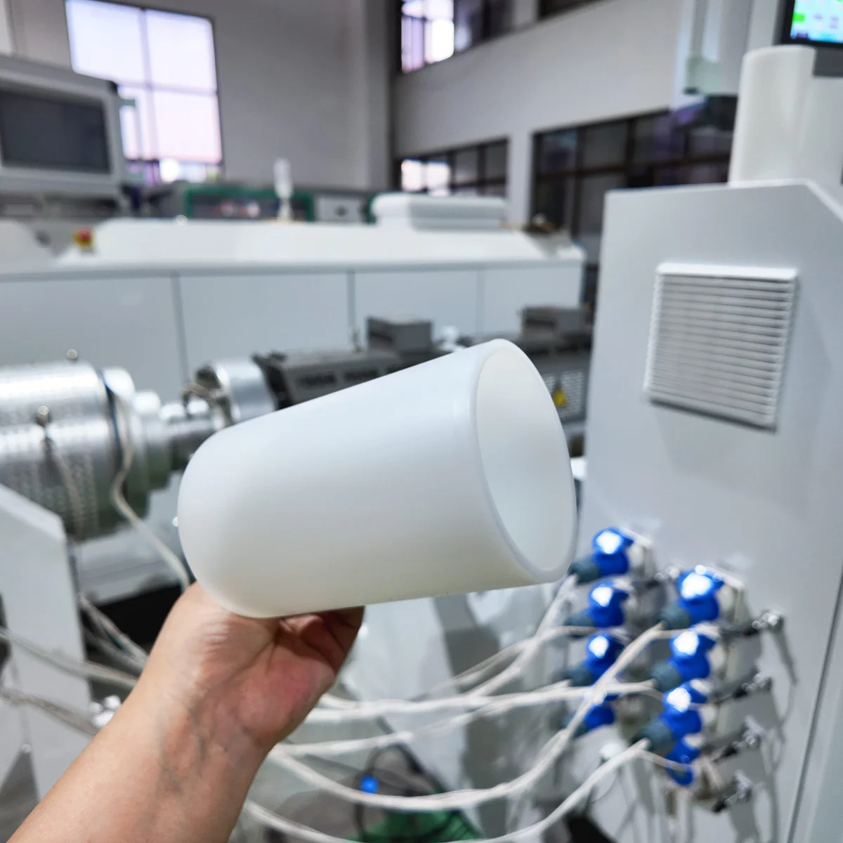
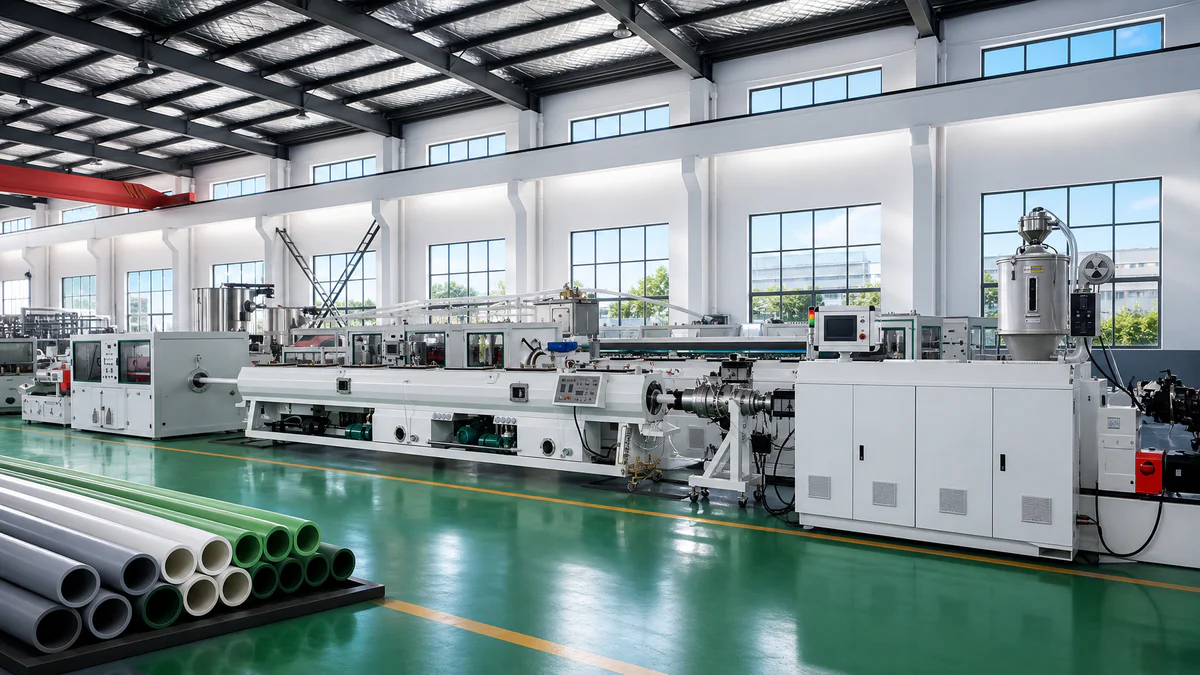
Dimensions and mating surfaces checked as the work moves.
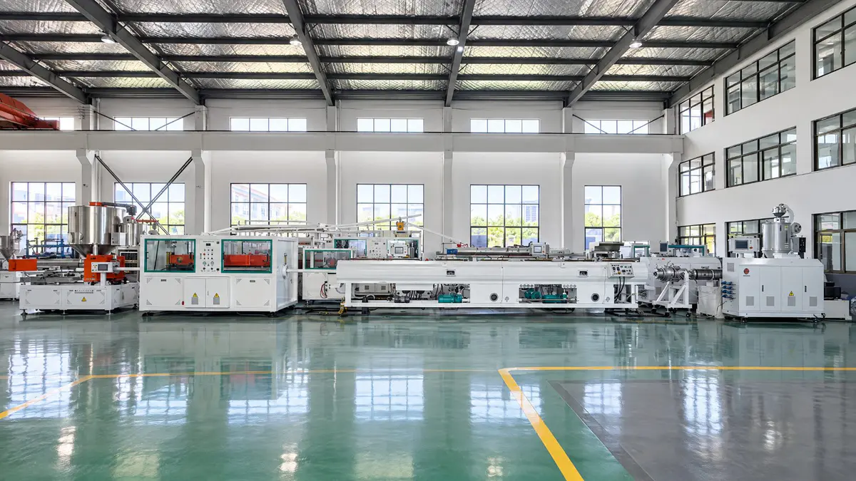
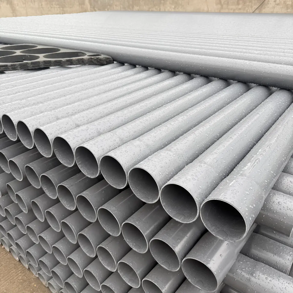
What Happens Between Drawing And Crate
Precision CNC Machining
The body and tooling are cut from solid against the confirmed drawing, including the interface that has to land on your extruder.
Internal Flow Channel
The channel your melt actually travels through. This is the part nobody sees on delivery and the part that decides how your pipe runs.
Grinding And Polishing
Flow surfaces and the die land are finished so material does not hang up and your pipe surface comes out clean.
Component Inspection
Each part is measured before it goes anywhere near assembly. A part that is out gets remade, not adjusted at the bench.
Assembly
Mating surfaces are checked as the head goes together, so it seals under pressure instead of only sitting flat on the table.
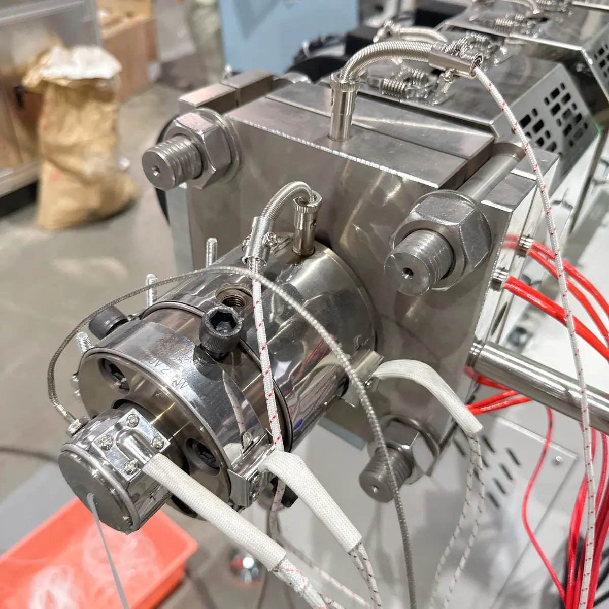
Heater Installation
Heaters and thermocouples fitted and wired for your voltage, so the head arrives ready for the electrics you already have.
Want to see a specific stage on your own order? We send production photos and machining progress during manufacturing, not only a shipping notice at the end.
What We Check Before Your Die Head Ships
Eight checks against the confirmed drawings and your project requirements. The focus is on whatever affects installation, adjustment and setup once the crate is opened at your factory.
01
Critical Dimensions
Key dimensions of the die body, die, mandrel and related tooling measured against the drawings you approved.
02
Extruder Interface
Flange dimensions, outlet connection, bolt pattern and mating surfaces, so the head lands on your machine instead of going back on a truck.
03
Die And Mandrel Alignment
Matching and positioning confirmed, so the tooling assembles and adjusts the way your operators expect it to.
04
Flow Channel Surface
Internal channels and polished surfaces checked for machining marks, damage or any area that still needs finishing.
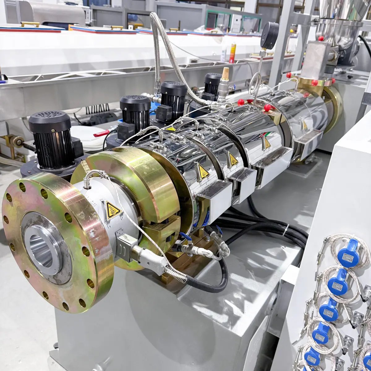 05
05
Heater And Thermocouple
Heaters, thermocouples and their mounting positions checked before the head leaves the workshop, not discovered on your floor.
06
Assembly And Adjustment
The head is put together to check component fit, fastening points and that the centering mechanism actually moves the way it should.
 07
07
Complete Tooling Set
Every die, mandrel, adapter and agreed item counted against the packing list, because a missing set is a stopped line.
 08
08
Drawings And Identification
Final drawings, tooling identification and the agreed technical documents, so parts can be matched during installation and the next size change.
Want the inspection records with your order? Ask for them at the start and we send the dimension check and photos of your own head before it is packed.
Decide How The Head Gets Accepted, Before It Is Made
For a replacement or custom head, the acceptance method has to match your real project conditions. Where a full production trial cannot be reproduced in our workshop, the dimensional and functional checks are agreed up front, instead of being argued about once the head is finished and both sides are already committed.
Workshop Acceptance
Checked against the drawings you approved and the requirements you confirmed. Six areas, all of them things you would look at yourself if you were standing at the bench.
Production Trial
Where suitable equipment, material and downstream conditions exist for your project, a trial can be agreed before manufacturing. Six conditions get written down first, so the result is not open to interpretation later.
The scope depends on the equipment and material available for your project. We will tell you plainly what can and cannot be reproduced here.
Four Sign-Offs, Then Manufacturing Starts
For a custom or replacement head, four things are confirmed before production begins. It leaves both sides with one document to point at during final acceptance, which is how disputes get avoided rather than settled.
Drawing Approval
Approved by you, not simply sent to you.
Acceptance Scope
The pass or fail list, written down in advance.
Manufacturing
Machining begins only once the first two are closed.
Final Check
Measured against what was agreed, nothing else.
Drawing
The full die head drawing, with your comments closed out.
Interface Dimensions
Checked against your actual machine, not a catalogue figure.
Inspection Items
The list your acceptance will be judged against.
Trial Requirements
Only where a production trial forms part of the agreement.
Tell us how you want the head accepted and we will put it in writing before the order is confirmed.
Pipe Extrusion Die Head FAQ
The questions buyers actually ask before they send a drawing. If yours is not here, send it to Maggie and you will get a straight answer rather than a brochure.
01
Can You Make A Die Head For My Existing Extruder?
Yes, but the interface gets checked before anything is machined. That check is what separates a head that bolts on from one that sits in your warehouse.
Send the extruder model, screw diameter, outlet dimensions, flange or bolt pattern, current material and output. A flange drawing is best. Clear photos of the connection work for the first review if no drawing exists.
02
What Information Do You Need To Design A Pipe Die Head?
Pipe material, OD range, wall thickness or SDR, pipe standard, required output and the production structure. That is the core set.
For an existing line, add the extruder model and outlet interface. For multilayer or colour stripe pipe, include the material and output of each extruder.
03
Can The Same Die Head Design Be Used For PVC, HDPE And PPR?
Not by swapping tooling alone. Each material fails in a different way when the flow design is wrong.
PVC needs attention on residence time, temperature and anywhere material can sit. PE and HDPE put the weight on circumferential distribution, pressure and output. PPR adds stable surface and wall formation. The internal flow design is selected around your actual material and conditions.
04
Can One Die Head Produce Several Pipe Diameters?
On many projects one die body covers a sensible group of sizes with selected tooling changed between them. The usable range depends on your material, diameters, wall thickness and required output.
Send the complete range you plan to run and we will tell you which components stay shared and which have to be size-specific.
05
Do I Need A New Die Head Every Time I Add A Pipe Size?
Not necessarily. If the new size sits within the practical range of your existing die body, additional die and mandrel tooling may be all you need.
Bigger jumps in diameter, output or process requirements can push you into a different configuration. Review the new size against your existing tooling before ordering parts, not after.
06
What Causes Uneven Pipe Wall Thickness?
Several sources, and the die head is only one of them. Uneven melt distribution, die and mandrel centering, die gap, temperature variation, unstable output or line alignment can all do it.
If one side stays consistently thicker, send measurements from several positions around the circumference together with your current die head and operating data. One reading tells us the wall is out. Four tells us where the melt is going.
07
Spiral Mandrel Or Spider Type, Which Is Better?
Neither is automatically better. Anyone who tells you otherwise is selling what they already have in stock.
The choice follows your pipe material, diameter, wall thickness, output and the balance you need between melt distribution, pressure, residence time and tooling structure. Pick the flow design from the pipe specification, not from the die type name.
08
Can You Design A Die Head For Multilayer Pipe?
Yes. A multilayer head is designed around the number of layers, the material of each layer, the target layer ratio, pipe dimensions and the output of the main and co-extruders.
Final layer distribution also depends on how stable and balanced your connected extruders are, so the complete co-extrusion setup gets reviewed together rather than the head on its own.
09
What Information Is Needed For Colour Stripe Pipe?
Number of stripes, stripe position, required width, colour reference, pipe OD, wall thickness and the co-extruder information.
If the stripe has to comply with a pipe standard or a colour specification, send that too. A finished pipe sample or a cross-section drawing is the fastest way to get a layout reproduced exactly.
10
What Should I Send When Replacing A Die Head That Is Causing Problems?
Send the pipe specification plus as much as you have on the current condition: existing die head drawing or photos, extruder model and output, pipe OD and wall thickness, the material you run, melt pressure and temperature if you record them, wall measurements, photos of surface defects or burnt material, and a description of the cleaning, centering or output problems.
The point is not to copy the old head dimensions. It is to work out why your current setup stopped meeting your production requirements, so the replacement does not inherit the same problem.
Question not covered here? Send it with your pipe data. Maggie answers technical questions in person, usually within 24 hours on business days.
Send Your Pipe Data To Maggie
Material, OD range, wall thickness or SDR, target output and your extruder model. That is enough for a real die head review and a quote back within 24 hours.

Maggie
Sales, QTech Machinery
Replies within 24 hoursEvery message from this page reaches me directly. Send your pipe data and I come back with a die head configuration, the tooling breakdown and a real quote, not a brochure.
If the head is not what is limiting your line, I will tell you that too, before you spend anything.
Maggie
Sales, Zhangjiagang Qinxiang Machinery Co., Ltd.
- Interface confirmed against your extruder before machining
- Tooling breakdown showing what is shared and what is size-specific
- Acceptance scope agreed in writing before production starts
- Your details stay private, no sales spam
Get Your Die Head Recommendation
Fields marked are required.